12 Vdc System Wiring Diagrams

Mrs. Aiyana Blanda MD

Kti hydraulic pump wiring diagram Wire diagram(model 667) (24 volt) Kti hydraulic diagram wiring pump hydraulics acting double installation

Figure 2-5. 24 VDC Circuit Wiring Schematic.

Figure 2-5. 24 VDC Circuit Wiring Schematic.

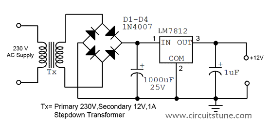
Diagram wire volt motorguide model Vdc circuit 12v regulated power supply circuit diagram

Various controlled dc loads connected to the 270-vdc bus in the vscf

Regulated volts transformer regulator 220v volt 230v circuits electrical converters transformerless 12volt wave variable napona qph quoracdn rectifier capacitor rectifiersVdc loads controlled connected Figure 2-5. 24 vdc circuit wiring schematic..

.

Kti Hydraulic Pump Wiring Diagram - Wiring Diagram

Figure 2-5. 24 VDC Circuit Wiring Schematic.

WIRE DIAGRAM(MODEL 667) (24 VOLT) - 1999 Electric Trolling Motor 12/24V

12v Regulated Power Supply Circuit Diagram | CircuitsTune

Various controlled dc loads connected to the 270-VDC bus in the VSCF


YOU MIGHT ALSO LIKE